

OKL Series PoL DC/DC Converters: The Bite-Size Power Bricks That Keep Your Board Cinematic

Global electronic component supplier ERSAELECTRONICS: Rich inventory for one-stop shopping. Inquire easily, and receive fast, customized solutions and quotes.
This long-form, engineer-friendly (but pop-culture-laced) guide is all about the OKL series of Murata non-isolated point-of-load (PoL) DC/DC converters—how they work, why they’re so deployable, how to size and lay them out, and what to watch for in real production builds. We’ll keep it fun, but every checklist here is meant to help you ship a robust board the first time.
.png?x-oss-process=image/auto-orient,1/quality,q_70/format,webp)
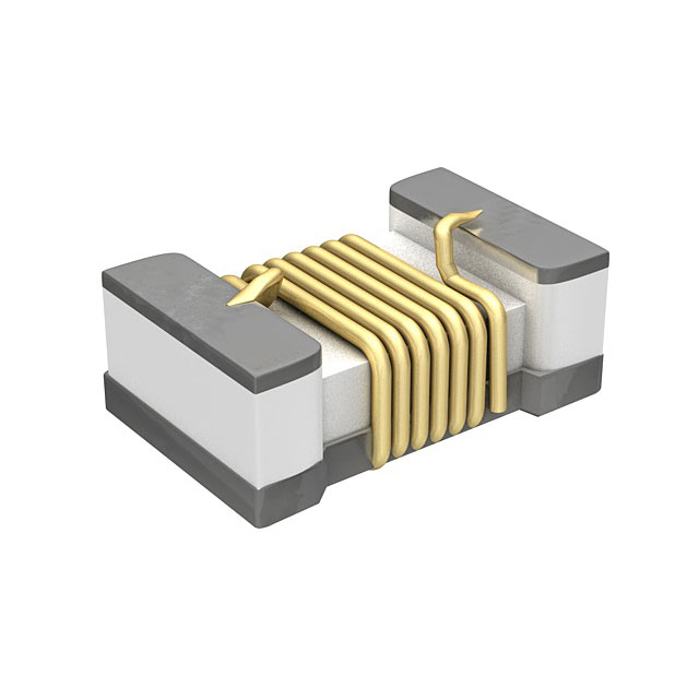
1) What Makes an OKL… an OKL?
At heart, an OKL module is a tiny synchronous buck converter delivered in an inspectable Land Grid Array—iLGA—that you drop next to your load. Every OKL is a self-contained PoL stage: wide input, programmable output, high efficiency, and a feature set that reads like a designer’s wish list (UVLO, short-circuit and over-current protection, remote on/off, Power Good, and—if you pick OKL2—sequence/tracking). These modules are built for embedded systems that juggle multiple rails and fast dynamic loads without burning a week on VRM tuning.
Why go OKL instead of a discrete buck? Sometimes you absolutely should build discrete (cost, volume, or unique constraints). But for a lot of CPU/FPGA/SoC designs, OKL buys you schedule, predictability, and “it just works” thermals in a package roughly the size of a keyboard keycap. Pro tip: engineers who’ve suffered one too many bring-ups with marginal stability often pivot to OKL for critical rails.
2) The OKL Cast: OKL-T vs OKL2-T (and why “2” matters)
OKL-T/… models: the baseline heroes—programmable Vout, on/off, protections, Power Good.
OKL2-T/… models: everything above plus optional sequencing/tracking, so you can choreograph multi-rail power-up like a Broadway opener (core before I/O, analog after reference, etc.). That one small “2” solves so many “why did my FPGA latch up?” tickets.
If your system includes a CPU + DDR + FPGA + high-speed PHYs, the OKL2 rail-tracking option is worth its weight in lab time. Pick OKL2-T/6-W12 when you want to keep power-up waveforms in lock-step.
3) Quick Specs You Can Hang Your Scope On
For the widely-used OKL-T/6-W12 and OKL2-T/6-W12 family (the ones many teams start with):
- Input range: 4.5 V to 14 V
- Output: Programmable 0.591 V to 5.5 V
- Current: up to 6 A (≈30 W)
- Efficiency: up to ~93% at typical operating points
- Footprint / height (max): ~12.2 × 12.2 mm, 7.2 mm tall
- Form factor: iLGA
- Perks: Power Good, remote on/off (positive or negative logic), optional sequence/tracking on OKL2, short-circuit & over-current protection
- Switching frequency: nominal ~600 kHz
- Capacitive load: drives up to 300 µF ceramic (ESR 1–10 mΩ typical guidance)
- Safety & compliance: UL/IEC 60950-1 (2nd Ed.), RoHS
Need 3 A instead of 6 A? The OKL-T/3-W12 variants hit similar notes at 3 A. There’s also OKL-T/3-W5 when your source is 5 V.
.png?x-oss-process=image/auto-orient,1/quality,q_70/format,webp)
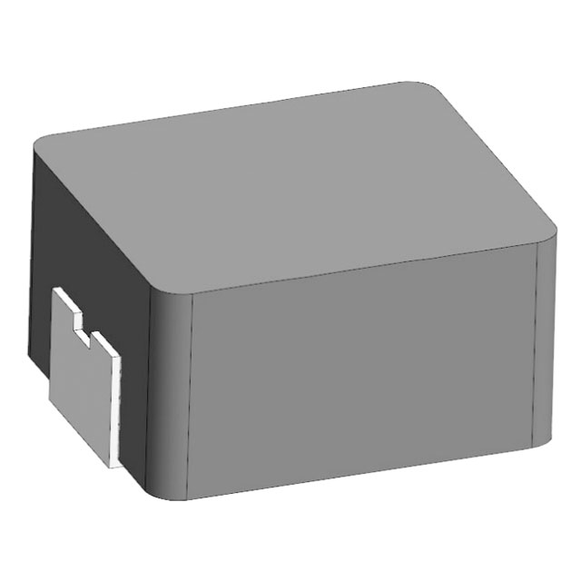
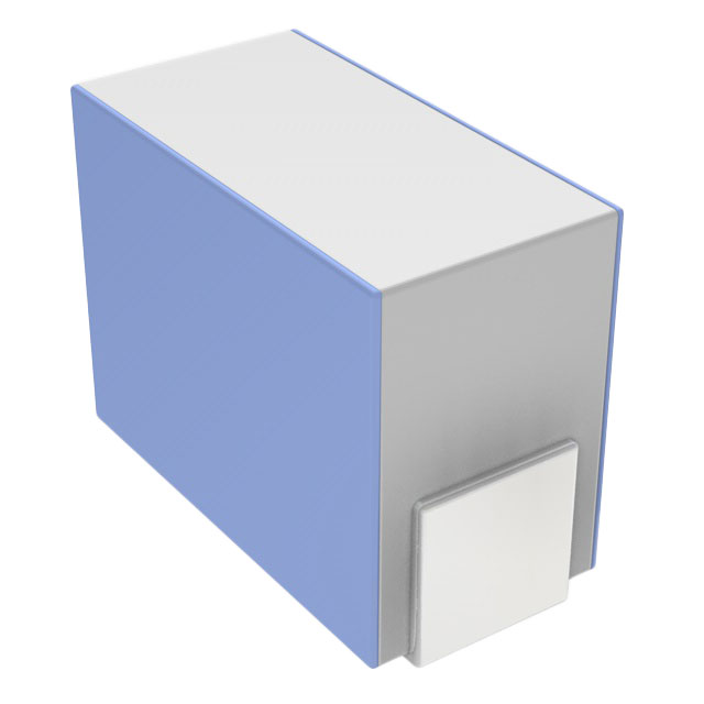
4) The iLGA Advantage: Why the Footprint Feels Like Cheating
Most PoL modules force you to choose: tiny but hard-to-inspect pads, or big and inspectable. The OKL series goes with iLGA: inspectable Land Grid Array. You get the density of LGA and the production sanity of visible toe fillets, easier AOI, and straightforward hand-rework if a single pad bridged during the Friday-night paste print. That’s a fancy way of saying: OKL is kind to your SMT line and your yield.
From a layout perspective:
- Place decoupling caps within a breath of the VIN/VOUT pads (think <3 mm loop).
- Keep the high-di/dt loop short and fat.
- Provide a quiet, low-impedance ground (split analog/digital returns intentionally).
- Give the OKL a thermal path to copper—more on that later.
5) Design-In: Picking the Right OKL for Each Rail
Let’s say your system runs from 12 V and you need rails at 5 V, 3.3 V, 1.8 V, and 0.9 V:
- 5 V @ 3–6 A (USB-PD hub, sensors, fans): OKL-T/6-W12 makes quick work of it. Start with Vtrim for 5.00 V, size output caps for your transient, and check the 300 µF ceramic guideline.
- 3.3 V @ 2–4 A (MCU, Ethernet PHYs): OKL-T/6-W12 or OKL-T/3-W12 depending on headroom. If you’re flirting with 4 A bursts, use the 6 A part for thermal margin.
- 1.8 V @ 2–3 A (DDR, PHY analog): OKL2-T/6-W12 plus tracking keeps 1.8 V aligned relative to core/3.3 V so memory doesn’t pull a drama-queen during ramp.
- 0.9–1.0 V @ 4–6 A (FPGA core): OKL2-T/6-W12 again—tune slew and tracking to your device’s datasheet sequence. Your validation team will high-five you.
Sizing tips you’ll actually use:
- Current: leave at least 25–35% headroom over sustained load; transient peaks are fine if within the OKL’s dynamic response.
- Efficiency/thermals: 93% is a headline—still verify copper area, airflow, and local heating.
- VIN: keep it comfortably inside the 4.5–14 V window, and mind UVLO. If your upstream 12 V sags, UVLO protects you—design your brownout budget accordingly.
6) Trimming & Sequencing: Teaching Your OKL Rails to Enter on Cue
Trimming VOUT
The OKL output is set with a resistor network to the TRIM/SET pin (see datasheet’s recommended equations). That 0.591 V lower bound is the internal reference; everything above is a ratioed derivative. For low-core rails, keep the sense leads short and Kelvin-ish.
Remote On/Off (positive or negative logic)
OKL lets you pick your personality:
- Positive-logic: ON when the control pin is high/open; OFF when pulled low.
- Negative-logic: ON when open/low; OFF when driven high. It’s a nice touch when you’re integrating with a pre-existing supervisor with “inverted” behavior. (Both modes are in the datasheet tables.)
OKL2 tracking/sequencing (the secret sauce)
With OKL2, you can track another rail during rise/fall or impose a sequence so one rail reaches 90% before others budge. That solves a dozen failure modes in SoC/FPGA bring-ups (ESD diodes between rails, analog references that must appear after digital, etc.). The spec notes ±100 mV tracking accuracy around the sequence signal—plenty for logic rails. Start with a modest slew (≤2 V/ms) and tighten only if your boot time demands it.
.png?x-oss-process=image/auto-orient,1/quality,q_70/format,webp)
7) Capacitors, Transients & Compensation: Let Your OKL Breathe
Input side
- Use a local ceramic 22 µF near VIN (datasheet’s test setup uses ≥22 µF plus a bus bulk cap), and provide upstream bulk if your source is remote.
- Keep ESL low—two 10 µF 1206s often beat one 22 µF 1210 in transient response.
Output side
The OKL family is stable with no load and can drive up to ~300 µF ceramic (very low ESR) or more if ESR is higher; match your transient target to the load step reality. The datasheet shares a ±2% within ~50 µs recovery figure for a 50→100% step at 1 A/µs—use it as a starting point and measure on your board.
Compensation
Because OKL is a module, you don’t expose the internal compensation network—but your effective loop still “feels” the load pole and cap ESR zero. Excessively low ESR with giant ceramics may increase peaking; mix in a modest ESR polymer if required. The datasheet’s capacitive load app note call-outs are worth a read.
Pre-bias startup
OKL handles pre-biased rails (won’t “suck down” an already-charged output). That’s golden when rails share downstream loads or when supervisors briefly back-feed.
8) Layout Like a Pro: The “Don’t Be the Villain” Checklist
Think of your layout like a heist sequence: the fewer turns and the shorter the hallway, the safer the loot.
- Shortest possible high-di/dt loop between VIN caps → OKL → GND return.
- Output caps hugging the VOUT and PGND pads; give the OKL a copper “patio.”
- Thermal vias under the module into an internal copper plane (no surprise hot spots).
- Star-ish ground discipline for sensitive analog loads; don’t let motor returns pollute your OKL ground.
- Keep sense/trim nets short and away from switch nodes.
- Place Power Good routing away from aggressors; it’s a logic-level net that shouldn’t act like an antenna.
9) Thermals & Derating: What the Datasheet Hints (and Your IR Camera Confirms)
The OKL datasheet’s derating curves assume nominal input and natural convection; they’re great for average current guidance. In real life, bursts are fine if the RMS stays under the curve and your copper spreads heat. If you mount OKL under a hood or in a tightly sealed enclosure, assume you’ll need either more copper, forced airflow, or both. The family boasts “outstanding thermal derating performance,” but that’s only true when the PCB does its share.
Quick thermal sanity checks
- 10-minute run at 80–90% of rated current, log peak temp on the package and nearby ceramics.
- Hit your worst-case VIN (e.g., 14 V into a 1 V rail at 5–6 A is a higher step-down ratio; look at switching losses).
- If a corner of the iLGA is notably hotter, you likely need more copper there (or an extra via farm).
.png?x-oss-process=image/auto-orient,1/quality,q_70/format,webp)
10) Protections & Power-Good: How OKL Saves You From Yourself
- UVLO: drops the converter when input sags below threshold—no “half-on” brown-outs.
- Over-current / short-circuit: hiccup auto-recovery so you don’t cook a trace while your tech hunts for the cause.
- Power Good (open-drain): asserts when VOUT is within about ±10% of setpoint—perfect for gating downstream enables or a reset sequencer.
Some listings note recommended external fuse ~10 A and no built-in reverse-polarity protection on the input, which is standard for non-isolated PoLs—respect polarity and add that upstream fuse on fielded systems. (If you’re designing for automotive or battery-edge rails, this is non-optional.)
11) Label Decoder & Ordering Notes (So You Don’t Buy the Wrong OKL)
Because an OKL is tiny, the product label compresses model and date info:
- Row 1: Murata Power Solutions logo
- Row 2: Model code (shortened)
- Row 3: 4-char date code
- Year = last digit (e.g., “9” → 2019)
- Month = 1–9 for Jan–Sep, then O/N/D for Oct/Nov/Dec
- Day = 1–9, “0” for 10, A–Z for 11–31
It’s a neat trick for traceability without a billboard label. Keep a decoding crib sheet in your build docs so incoming QA doesn’t play Wordle with your parts.
Ordering sanity
- P vs N in the part number often denotes positive vs negative on/off logic (e.g., OKL-T/6-W12P-C vs OKL-T/6-W12N-C). Check your supervisor polarity before you buy.
- OKL2 suffix indicates the sequencing/tracking feature. If your BOM mistakenly swaps OKL-T where OKL2-T was required, your rails will power up… but not in harmony.
12) System Playbooks (CPU, FPGA, Telecom, Robotics, Audio, Solar-Edge)
A) CPU + DDR on a gateway board
- 12 V bus → OKL-T/6-W12 @ 5.0 V for USB + fans
- 12 V bus → OKL2-T/6-W12 @ 3.3 V (tracks 5 V)
- 12 V bus → OKL2-T/6-W12 @ 1.2 V (core) with delayed sequence
- Power Good lines feed a tiny CPLD reset tree.
Result: zero latch-up, repeatable boot.
B) Mid-range FPGA carrier
- 12 V brick → OKL2-T/6-W12 @ 0.9–1.0 V (VCCINT)
- 12 V brick → OKL2-T/6-W12 @ 1.8 V (aux) tracking core
- 12 V brick → OKL-T/6-W12 @ 3.3 V (I/O)
- Use the OKL2 tracking to guarantee core precedes I/O; fans run off the 5 V OKL rail with a small soft-start. Stability solved, validation smiles.
C) Datacom/telecom line card
12 V backplane → a bouquet of OKL rails sprinkled near each load island. Hot-plug events muted by stout input ceramics and a slim TVS at the backplane; each OKL has its own VIN bulk local. No cross-talk, no sag.
D) Robotics/AGV
14 V battery swings are real; design for 4.5–14 V input window with upstream protection. Use OKL for low-voltage logic islands; keep motor drivers on their own filtered branch. OKL UVLO saves you from brown-outs when the pack dips.
E) Audio head-unit / amplifier control
Keep MCU, Bluetooth, and DSP rails clean with OKL-T modules; sequence analog rails last to avoid thumps. OKL’s 600 kHz switching stays out of most audio bands, and you can still filter the output if your codec is picky.
F) Solar-edge controller
12 V nominal bus → OKL rails for logic and comms; choose IP-rated enclosures and add that external input fuse. If your enclosure bakes, plan copper and airflow—even tiny PoLs deserve a breeze.
.png?x-oss-process=image/auto-orient,1/quality,q_70/format,webp)
13) Validation Plan: From Bench Bring-Up to HALT-Lite
A. Bench bring-up
- Power with current-limited lab supply at 12 V, no load; confirm Power Good high within ±10% window.
- Step loads at 25%/50%/100%; log recovery time and peak deviation.
- Scope ripple with 20 MHz bandwidth limit; probe right at the output caps.
B. Dynamic & sequencing
Emulate worst-case rail-up: verify OKL2 tracking slopes and hand-offs. Document the exact millisecond timeline for each rail.
C. Thermal
30–60 minute steady state at 80–90% of rated load. Take IR snapshots every 10 minutes. If you see >100 °C case in still air, add copper or airflow.
D. Corner cases
- UVLO sweeps (simulate low battery or droop). Confirm clean drop and recovery—no oscillatory flapping around the threshold.
- Short-circuit test (momentary and sustained): watch hiccup behavior and auto-recovery; verify the upstream fuse doesn’t nuisance-blow during a brief fault.
E. EMI pre-check
Near-field probe around the OKL while banging the load step. If a hot spot sings, nudge the copper and snub what needs snubbing.
Closing Scene
Your PCB is a universe of hungry subsystems. The OKL series is how you feed each one like a pro—close to the load, predictably, and with enough features to keep chaos politely outside the chassis. Use OKL where you need fast, efficient rails; use OKL2 when order matters. And if your validation engineer smiles during bring-up? That’s the kind of cinematic ending we all root for.
© 2025 Ersa Electronics — HTML version of the OKL series article with anchor links and image placeholders.

 FAQ
FAQ


.png?x-oss-process=image/format,webp/resize,h_32)


